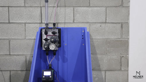
How to Perform a Pump Calibration Using a DICE™ Chemical Dosing Modules DS
A pump calibration can be performed to calibrate the pump with proper operating conditions or to troubleshoot the dosing system. Calibrating the pump using the DICE™ chemical dosing module DS is a simple and safe procedure that does not require any tools.
Carefully read the DICE™ DS Installation, Operation and Maintenance Manual before proceeding with a pump calibration.
Understanding Pump Calibrations
Proper Operating Conditions
The DICE™ configuration allows the pump to be calibrated with the proper operating conditions.
During the calibration, the dosing pump sees the actual suction pressure (dependant on the tank level) and the correct discharge pressure maintained by the back pressure valve.
Troubleshooting the System
The pump calibration can also be done to troubleshoot the dosing system. It allows the operator to quickly validate that the system is operating properly and that the fluid is flowing from the chemical tank to the back pressure valve outlet.
If there is an issue with the injection line or the injection quill, the problem can be located quickly and corrected to ensure an optimal operation of the dosing system.
Calibrating the Dosing Pump
Prior to performing the pump calibration, the pressure relief valve and the back pressure valve should be adjusted. Refer to the DICE™ DS installation and setup video.
To perform a pump calibration, the first step is to close the injection outlet ball valve and to open the calibration cylinder ball valve (make sure the evacuation valve is in the closed position). The following illustration shows how the valves should be set for the calibration.

Start the pump and fill the calibration column to its first measurement line. Then, start the calibration sequence by filling the calibration column while measuring the time and volume (refer to your dosing pump manufacturer calibration sequence).
Once the pump calibration is complete, simply close the calibration column and the evacuation ball valve. Reopen the injection ball valve.
The ball valves should now be in the same position than before the pump calibration. The system is now ready to operate.