How to Install, Setup and Adjust the DICE™ Chemical Dosing Modules ES
The installation and the setup of the DICE™ chemical dosing modules are quick and simple. Installing the DICE™ ES can be done in less than 15 minutes and it does not require any specific tools.
Carefully read the DICE™ ES Installation, Operation and Maintenance Manual before installing, starting up and servicing the module.
Installing the DICE™ in Two Simple Steps
The DICE™ dosing module installation can be accomplished in two steps: the DICE™ support installation and the tubing connections.
There is more than one way to install and integrate the DICE™ ES on your dosing pump. It depends on your application, but it is the same procedure. The ordered model number reflects the chosen connector configuration, the pressure rating, and the material configuration.
Installing the DICE™ Support
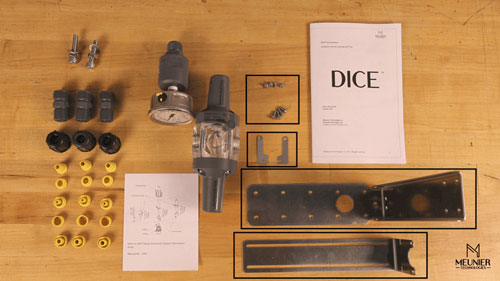
The first step is to install the DICE™ support. To proceed, you need to use the upper bracket, the lower bracket, the two tabs and the two sets of mounting screws.

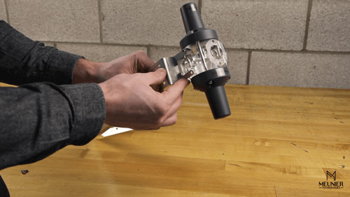
Start by installing the upper bracket on the DICE™ module using the two mounting screws. Make sure to install it on the bottom face of the module, the bracket facing the back (refer to the video if unclear).
Install the two linked plates on the DICE™ using two mounting screws. Insert the two linked plates bottom portion into the upper bracket grooves as shown in the following illustration. The recommended torque to be applied is 60 oz-in.

Assemble the upper bracket on the lower bracket using the four remaining mounting screws. However, make sure not to completely tighten the screws. This will allow the brackets to slide and adjust for final height later.
When the DICE™ support is completed, install the back pressure valve and the pressure relief valve adjustment screws. Then, install the supplied pressure gauge and isolator on the front of the DICE™ dosing module.
The Tubing Connections
Install the supplied ferrule connectors on the three following ports: on the top, on the bottom, and on the back. Firmly tighten them. The connectors should be hand tighten or with a maximum torque of 20 in-lb.
Note:
Make sure to install the ferrule connectors on the correct side. If the connector is not held properly once you screwed it in place, reverse it. Screw the opposite side of the connector into the DICE™ module. The connector should now be sturdy and well supported.
Now that the connectors are installed, proceed with the following connections: the dosing pump, the process outlet line, the tank return line and the pump inlet.
- Before mounting the dosing pump, secure the lower bracket in place by using the lower bracket mounting holes.
To connect the pump to the DICE™ dosing unit, simply cut a short piece of tubing and use the supplied ferrule kits to proceed with the connection.
Lift the module at the correct height, and install the hose on the pump outlet and the DICE™ inlet. You can now adjust the final bracket height and tighten the four assembly screws. - For the process outlet line, install the injection tubing on the DICE™ outlet using the supplied ferrule connector.
- For the tank return line, connect directly the tank return line on the supplied ferrule connector.
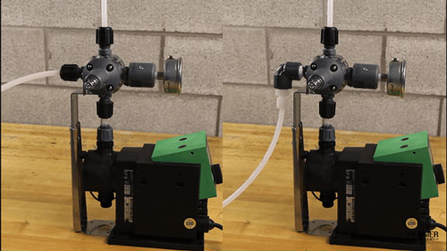
Optional: Tank return line with elbow
If required, the tank return port located on the back of the DICE™ ES can be equipped with a preassembled elbow and hose connector.
The exemplary preassembled elbow is made using the same supplied DICE™ connector which has a 1/2” NPT Male end, a 90 degrees elbow with female NPT connections and a hose connector. This assembly can be supplied if requested.
In this optional case, the tank return line will be connected directly on the preassembled elbow and hose connector.
The installation should look like the following illustration.

4. Install the pump inlet tubing using its ferrule connector.
Once you completed the installation, proceed with the setup and adjustment.
Please note that the DICE™ ES can also be supplied with a wall mount bracket. The installation procedure follows the same guidelines.
The Setup and Adjustment
The DICE™ chemical dosing module ES setup and adjustment requires two simple steps:
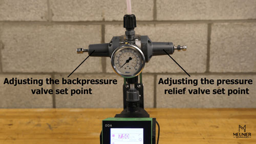
- adjusting the pressure relief valve set point;
- adjusting the back pressure valve set point.
It can be accomplished in a few minutes.

To begin, completely screw the back pressure valve adjustment screw. Then, start the dosing pump and wait until the fluid starts flowing through the pressure relief valve.
- Adjust the pressure relief valve set point using its adjustment screw. For this demonstration, the set point is 100 psi.
- If your system is equipped with an injection outlet isolation valve, open it. Then, adjust the back pressure valve set point using its adjustment screw. For this demonstration, the set point is 70 psi.
To complete the setup, simply torque the counter nut on both the back pressure valve and the pressure relief valve. The back pressure is now set to 70 psi and the pressure relief to 100 psi.
Then, your DICE™ chemical dosing module is fully setup and ready to operate efficiently.